Model preparation
Accurate daylight analysis depends on correct Revit model structure. Check the following before running an analysis:
- Ground Level: correctly detected, or set manually in Analysis Settings.
- Room Clusters: Room Separation Lines only connect physically adjacent rooms.
- Windows & Doors: openings sit in the wall bounding their room, the wall's Function is Exterior, and glass is detected correctly.
- Floor Separation: interior floors and exterior balconies are modeled as separate elements.
- Obstructions: Context Categories and Context Worksets include the elements that block daylight to the analyzed rooms.
- Design Options: the option to analyze is chosen per option set, if not the primary one.
- Phases: all rooms and components to analyze are in the same phase.
Ground Level (Terrain)
For accurate analysis, the plugin must identify the Terrain Level (ground plane). It uses a semantic scan of level names across four priority tiers.
How LUX detects the Ground Level
- Swedish Priority: "Plan 10", "Entréplan", "BV".
- International Terms: "Ground Floor", "GF", "00", "Erdgeschoss".
- Shortest Name Rule: If multiple levels match the same priority tier (e.g., "Plan 10" vs. "Plan 10 - Side Entrance"), the level with the shortest name is selected.
- Geometric Fallback: If no name matches, the level closest to elevation 0.00 is selected.
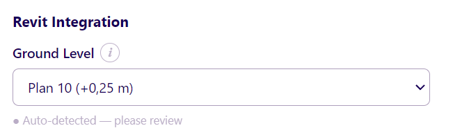
The detected level appears in Analysis Settings, under Revit Integration. If it is incorrect, select a different level there. A manually set level is used for the analysis, saved with the project, and synced to other users through Worksharing.
Verify the result in the 3D Viewer: the room property "Height over Terrain" is the vertical distance from a room's floor to the terrain level, and the horizontal grid aligns with the detected Ground Level for a quick visual check.
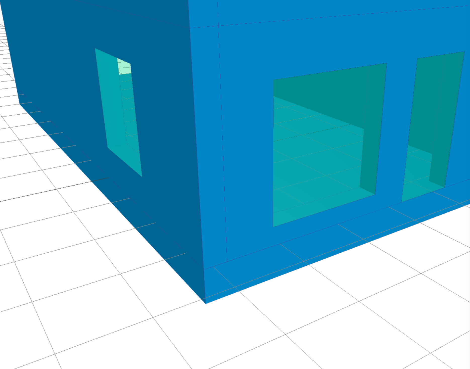
LUX uses one Ground Level for the entire project. In buildings with different ground access on different sides, for example a sunken courtyard on one side and a street-level entrance on another, use an averaged level. Its impact on results is small. If accuracy for a specific side matters more, set the Ground Level to that side's terrain and run a separate analysis for its rooms.
Room Clusters
A Cluster is defined as a group of rooms connected by Room Separation Lines. All connected spaces are treated as a single geometric unit for the analysis. The Log and 3D Viewer list all detected clusters. If a cluster contains more than 5 rooms, a warning dialog appears during the analysis. This is a quality notice to help you identify potential issues, such as missing walls or incorrect separation lines. You can proceed with the analysis if the cluster is intentional.
Modeling Best Practices
For reliable results, Room Separation Lines should only be used between rooms that are physically adjacent. Avoid drawing long, continuous lines that span across multiple non-touching rooms, as this forces LUX to treat them as a single cluster.
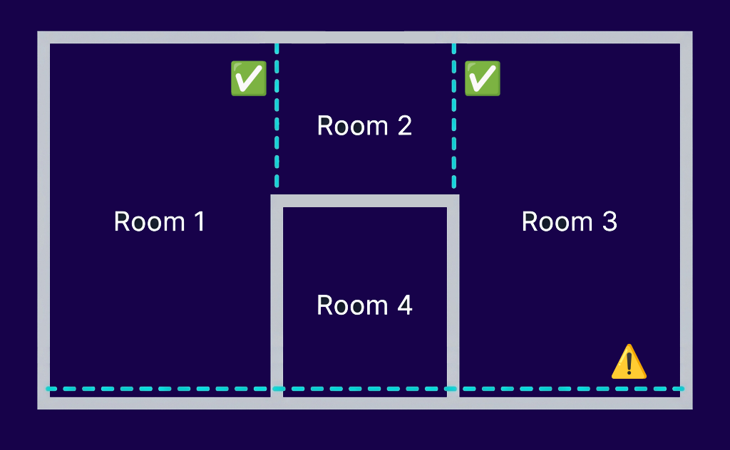
If your model requires complex separation logic, enable Extended Cluster Detection in Analysis Settings, under Revit Integration. However, maintaining clean, localized room boundaries is the best practice for accurate analysis.
Windows & Doors
For the plugin to correctly associate openings with rooms and calculate daylight, families must be modeled with specific properties.
LUX relies on Revit's FromRoom and ToRoom properties to identify which room an opening element belongs to. Ensure windows and doors are placed directly in the wall bounding the room. If an element is not detected, enable the "Room Calculation Point" in the family editor and ensure the point is located inside the correct room volume.
The host wall's type must have Function set to Exterior. A window in a wall classified as Interior is not treated as an exterior opening: it is excluded from the analysis.
Glass Detection (Glass/Frame Ratio)
To accurately calculate the transparent area (Glass/Frame Ratio), the plugin analyzes the family geometry using a priority order.
How LUX detects glass
- Sub-category/Name: Elements named "Glass" or "Glas".
- Material: Elements with a material named "Glass" or "Glazing".
- Transparency: Elements with a transparent material property.
- Geometric Heuristic (Fallback): If none of the above are found, LUX interprets the thin, center-most geometry as glass.
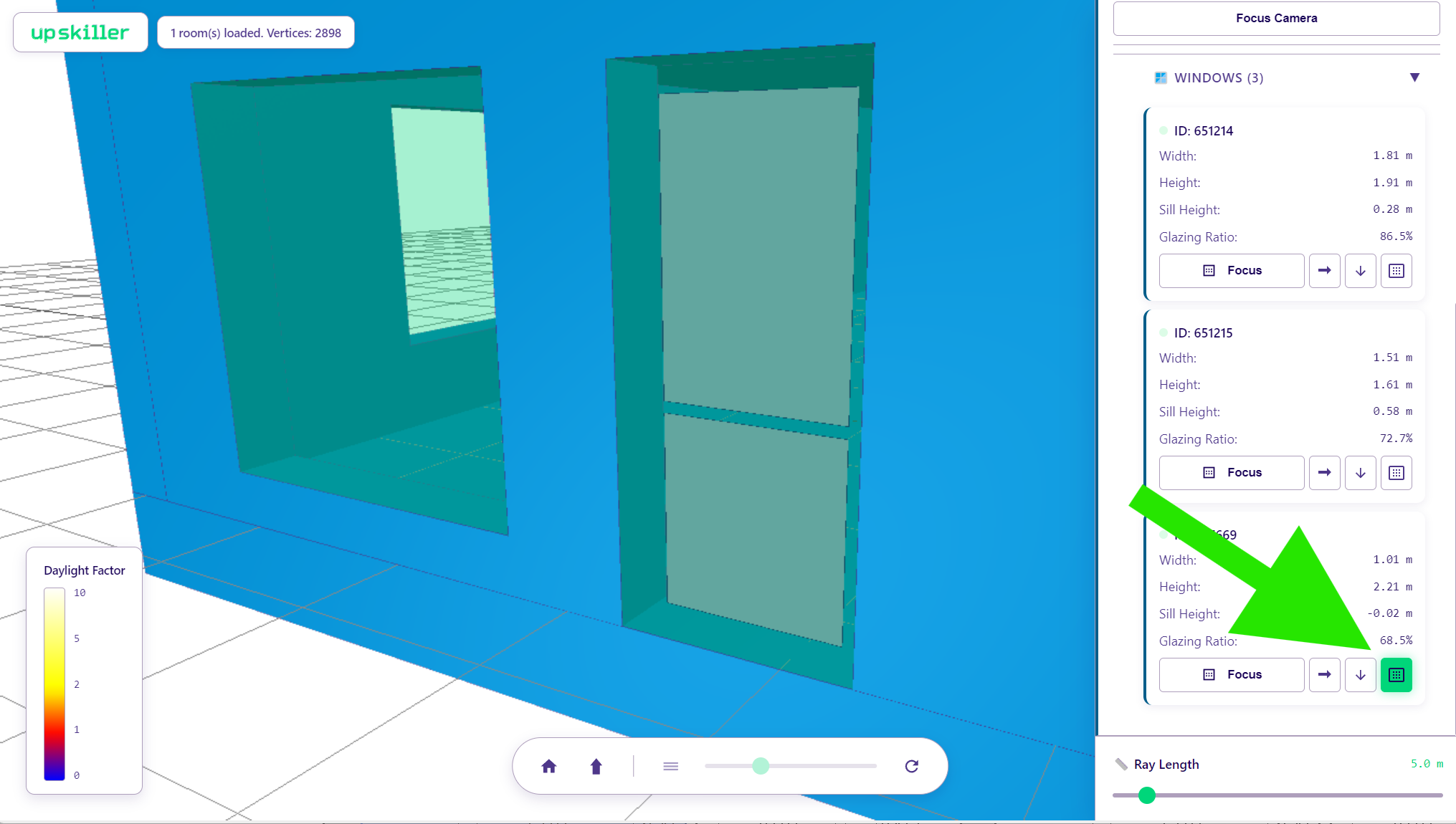
Verify the detected glass area in the 3D Viewer by enabling the "Glass" layer. If the detection is incorrect (e.g., solid panels detected as glass), adjust the family's material settings.
Floor Separation
LUX exports all floor elements for analysis. For optimal data organization and verification in the 3D viewer, model interior floors and exterior balconies as separate elements. The calculation works in both cases, but separation helps identify specific floor properties.
Obstructions
LUX determines which elements cast shadows on analyzed windows. Two independent sources contribute this geometry: the current document (Internal Context) and linked Revit models (External Context). Rule of thumb: an element counts as an obstruction if it blocks a substantial part of the sky as seen from inside the analyzed rooms - this includes the building's own mass, roofs and exterior walls, not only neighboring site context. Revit's Planting category, where trees and vegetation are normally modeled, is ignored.
Turn off specific categories or worksets under Context Categories and Context Worksets in Analysis Settings when they contain elements that would interfere with a correct analysis. Design Options controls which set of elements is considered in the first place.
External Context
Geometry from linked Revit models is simplified to two shading elements:
- Roofs and Floors are always included. Both extrude down to the Ground Level, deriving a simplified shading geometry, so linked walls are not needed and are not used as shading geometry.
- Mass is included or excluded depending on the Context Categories setting below, included by default.
The plugin only processes geometry from links that are currently loaded. A linked model is skipped entirely if its workset is excluded (see Context Worksets) or if it sits on a design option outside the current selection (see Design Options).
Internal Context
Geometry from the currently open document follows different rules per category:
- Roofs and Floors are always included.
- Walls are included only if their type has Function set to Exterior.
- Mass and Generic Models are controlled by the Context Categories setting below, Generic Models are excluded by default.
Context Categories
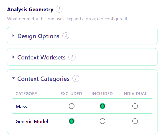
In Analysis Settings, under Analysis Geometry > Context Categories, choose a mode for the Mass and Generic Model categories:
| Mode | Meaning |
|---|---|
| Excluded | The category is not used for shading. Default for Generic Model. |
| Included | Every element of the category is used. Default for Mass. |
| Individual | Only elements you mark explicitly are used. |
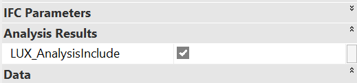
Choosing Individual adds a Yes/No instance parameter, LUX_AnalysisInclude, to elements of that category under Analysis Results, once you run an analysis. Set the category to Individual, run an analysis, then set the parameter to Yes on the elements that should cast shadows, everything else in that category is ignored. This also works for linked elements, provided the parameter exists in the linked model too.
Be careful with Generic Models: detailed elements or elements with rounded shapes produce a high triangle count and can slow down the analysis significantly.
Context Worksets
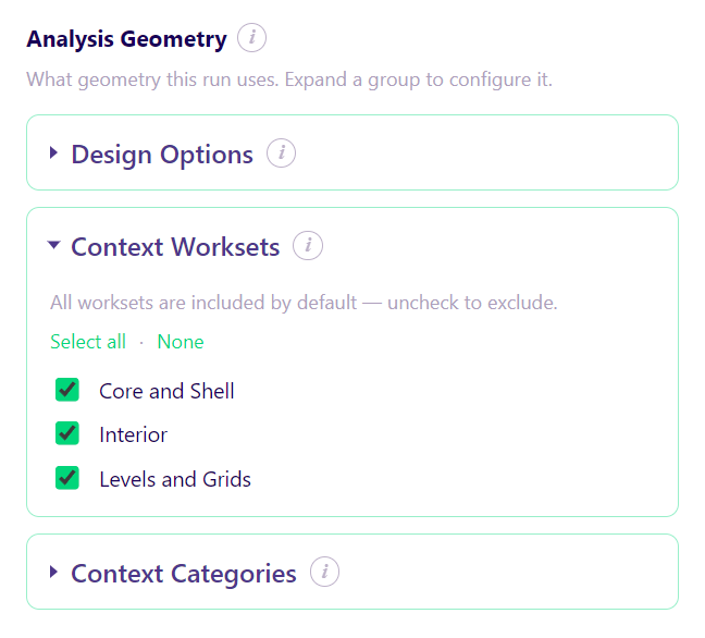
On workshared projects, Context Worksets excludes specific worksets from contributing shading geometry. All worksets are included by default, uncheck a workset to exclude it. This only affects which elements cast shadows, it does not affect which rooms, windows, or doors are analyzed. A closed workset cannot contribute geometry even if it is not excluded.
Design Options
By default, LUX analyzes the primary option of every design option set, plus anything in the Main Model. This happens automatically, no change is needed in Revit's own Design Options dialog. To analyze a different option, open Design Options in the LUX Analysis Settings panel and pick the option per set there. This choice is saved with the project and shown in the PDF report, independent of whichever option is active in Revit's own Design Options dialog.
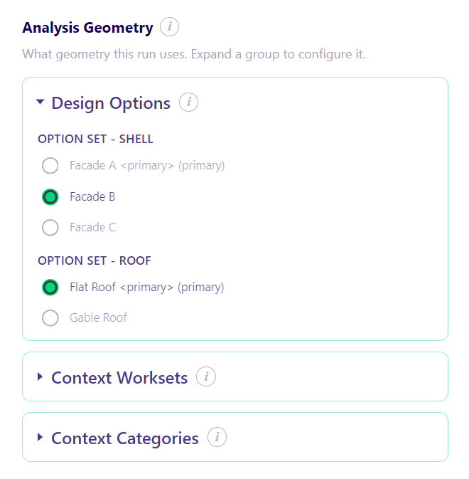
This selection applies to everything LUX collects from the current document: rooms, windows, doors, walls, floors, roofs, masses, and generic models. Linked models always use their own primary option, this cannot be changed per link.
Phases
LUX does not use one global active project phase. Instead, each analysis run uses the phase of the rooms you selected. All selected rooms must belong to the same phase, if rooms from different phases are selected, LUX stops before making any changes and asks you to select rooms from a single phase.
Within that phase, LUX also ensures that surrounding walls, floors, and roofs used for measurements (e.g. window reveal depth, sill height) reflect the model as it exists at that phase. Elements not yet built, or already demolished, at the selected rooms' phase are ignored for those measurements.
Place all rooms and components you want analyzed together in the same phase, and make sure the design options you intend to analyze are either each set's primary option or explicitly chosen in Design Options.
Troubleshooting
If the analysis completes with warnings related to model setup, such as missing room boundaries, unresolved wall functions or geometry extraction failures, consult the Warning Catalog for causes and solutions.